
Simplifying Infrastructure - The functional composed repository pattern that scales (Part 4)
A self-similar approach to organising infrastructure repositories and making the highly complex, manageable.

Clouds are not spheres, mountains are not cones, coastlines are not circles, and bark is not smooth, nor does lightning travel in a straight line.
— Benoit Mandelbrot
Imagine (the great mathematician) Benoit Mandelbrot sitting before a computer screen, zooming into the Mandelbrot set, watching as each level of magnification reveals new patterns of infinite complexity. After hours of exploration, he turns away from fractal geometry and observes an engineering team struggling to coordinate infrastructure changes across dozens of repositories. With a knowing smile, he says:
"You see the same pattern here as in mathematics - the whole contains the parts, and each part contains the structure of the whole. Your infrastructure repositories should reflect this fractal nature. Organise them not by technical boundaries, but by functional domains, where each domain is self-similar to the entire system yet serves its unique purpose."

This concluding part unveils the functional composed repository pattern - a self-similar approach to infrastructure organisation that scales from simple resources to enterprise platforms without exponential complexity growth.
You’ll discover why functional boundaries create natural scaling points, and how this composed repository self-similar approach eliminates the coordination overhead that kills infrastructure velocity. This article is very AWS centric, but its principles can be extrapolated to other cloud platforms or software and infrastructure vendors.
This four-part series breaks down how I build Terraform CI/CD for complex shared infrastructure, in a simple way, that works in the real world:
Part 1 exposes why your current tooling is probably fighting against you:
Part 2 discussed how vanilla CI/CD pipelines can handle the most complex infrastructure deployments without specialised tools;
Part 3 looks into branching strategies, and explores my personal preference for GitLab Flow for complex infrastructure, while allowing developer teams to use whichever strategy they prefer;
Part 4 (current post) reveals the functional composed repository pattern that organises this vanilla approach for maximum scale and minimum coordination overhead, taking inspiration from fractal geometry.
Main Insights
Self-similar organisation is intrinsically scalable: Functional domains contain self-similar structure that works at any scale (e.g. Landing Zones, Core Networks, Tenant Management, MLOps, etc);
Natural boundaries prevent coordination overhead: Related infrastructure changes together, unrelated systems evolve independently;
Self-similarity enables standardisation: Each functional domain follows the same deployment patterns (i.e. Infrastructure and Applications are not the same thing);
Scaling through replication, not complexity: Add new domains rather than expanding existing ones beyond their natural boundaries.
The self-similar nature of infrastructure
Mandelbrot’s greatest insight was recognising that complex natural systems exhibit self-similarity at different scales - coastlines, mountain ranges, and cloud formations all contain patterns that repeat whether you’re looking from space or through a magnifying glass. Infrastructure exhibits this same self-similar property, but many organisations aren’t even aware of this property.
Before we go any further, let’s discuss the spectrum of how infrastructure code (stacks & modules) tend to be organised in the modern enterprise. At one end you will find extreme fragmentation composed of countless micro-repositories that contain individual stacks and modules; At the other end you will find a mono-repository containing the entire code base for an organisation, which brings a wide range of technical challenges.
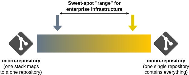
My experience shows me that a happy medium can be found: Organise complex infrastructure domains in composed repositories aligned by business purpose, team, and function; Allow tenant / application repositories to be smaller and autonomous (i.e. micro-repositories with template components) to reduce inter-team dependencies and blast radius.
Deploying the latter at scale and ease is a well understood and solved problem. We will now look into solving the former.
Understanding the relation with Fractal Geometry
Conway’s Law states that an organisation’s communication structure inevitably becomes reflected in the system it designs. This means that fragmented or silo’ed communication within a company will likely result in a fragmented or silo’ed technical system.
With Conway’s Law in mind, the first level of our system should reflect how teams and functions are grouped and aggregated - the composed repository. As an example, we could have the several repositories owned by the relevant teams: AWS Landing Zone repository, AWS Cloud Networks, Observability, Data Lakehouse, etc. Each repository contains the code and logic needed to deploy and operate its infrastructure.
At the top level of the composed repositories, we then find a folder hierarchy for our shared infrastructure stacks (in the case of a Landing Zone, this could be IAM, KMS, Logging, Security, etc), managed by an orchestrator CI/CD pipeline which triggers sub-pipelines based on stages and stack dependencies across hierarchies. This level can be repeated across the repository folder organisation depth, depending on the requirement moving parts - I mostly see 1 to 2 levels in my real-world implementations of complex shared infrastructure, and in some cases 3 levels (the maximum in GitLab).
Finally, at the end of the folder structure you will find individual Terraform stacks that compose the subdomain (explained in part 2 of the series) and their code promotion implementation in their CI/CD pipelines (explained in part 3 of the series).
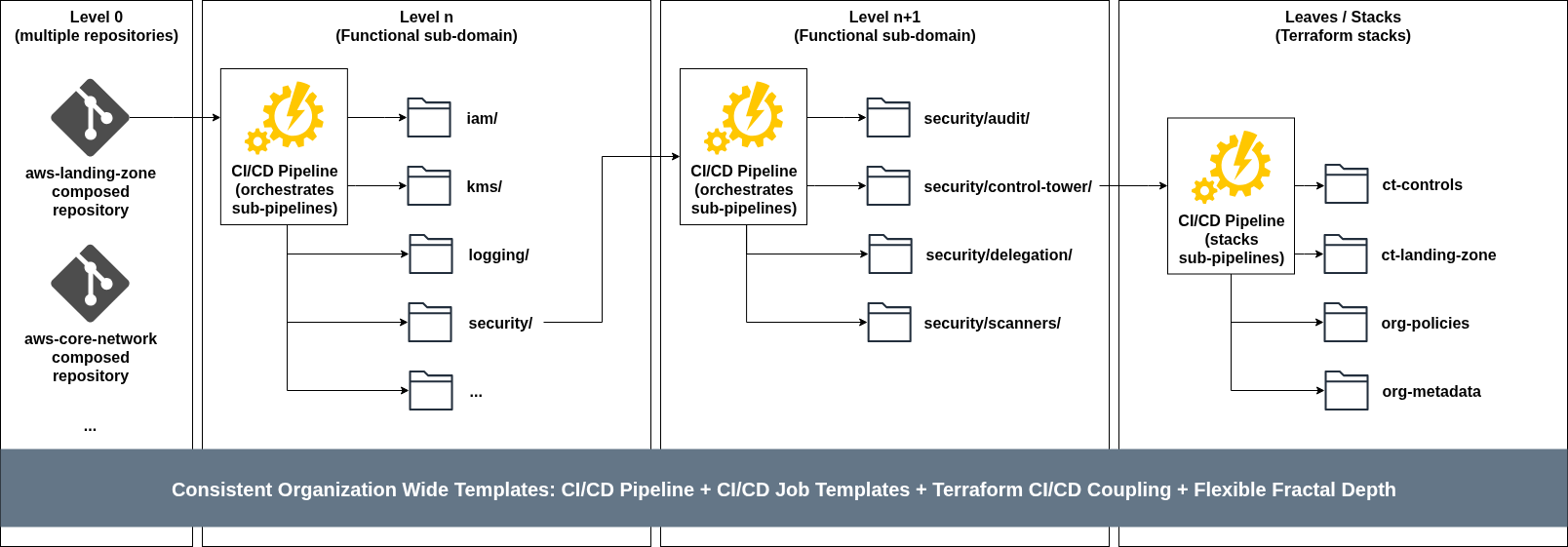
The insight is that each repository contains the same patterns, templates and mechanisms, but its organisation is based on individual team / functional domain needs and circumstances.
This self-similarity means that whether you’re managing an enterprise Landing Zone, a Data Lakehouse, or a Global Core Network, the repository structure and templates remain consistent while allowing the structure to evolve freely. Engineers can move between domains and immediately understand the layout, deployment process, and interaction patterns.
This architecture follows key principles that enable uncomplicated scaling:
Modular Construction: Projects are built in modular ways so you can orchestrate business or operational flows that touch different projects. Similarly, projects may be composed of sub-projects;
Single or Multiple Stacks: A project can be made of a single or multiple Terraform stacks, depending on complexity and deployment requirements;
Scope-Specific composed-repositories: Build scope-specific repositories grouped by a combination of business scope and operational scope;
Business and Operational Alignment: Repository boundaries should align with both the business purpose (what it accomplishes) and operational scope (who manages it);
Two distinct types of repositories exist in this architecture, each serving different purposes with different levels of autonomy: Centrally Managed and Tenant / Project repositories.
Centrally managed repositories
These represent the dense, high-control regions of the system - common infrastructure elements that govern and implement the overall cloud setup:
Landing Zone: Foundation infrastructure, Control Tower, organisational structure and security policies;
Core Network: Global networking fabric, Network Firewall, DNS;
Tenant Project Administration: Account creation and provisioning,, baseline configurations, governance, and project customisation;
Observability: Centralised logging, monitoring, alerting and application tracing infrastructure;
Central Data Management: Shared data platforms, data lakes, analytics infrastructure;
Source Code Management: GitHub/GitLab administration, repository governance and management;
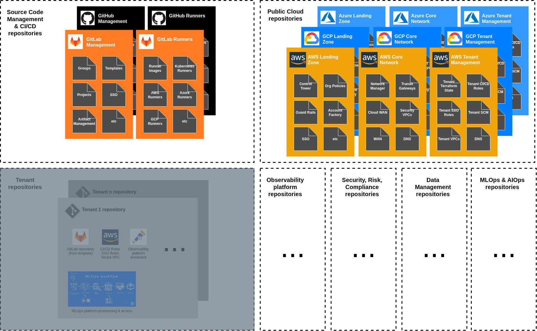
These repositories have maximum autonomy because they’re owned by the central teams (e.g. Cloud Center of Excellence, Cloud Networks, Data Management, etc). They can implement complex logic, maintain extensive configuration, and evolve rapidly based on their own platform requirements.
Tenant / Project repositories
This is where you would find your business application code and deployment logic (micro-repositories, or consolidated).
These represent the sparse, constrained regions of the system - repositories owned and managed by different workload and application teams. They’re designed for specific applications and infrastructure needs but operate within the boundaries and guardrails established by the central teams.
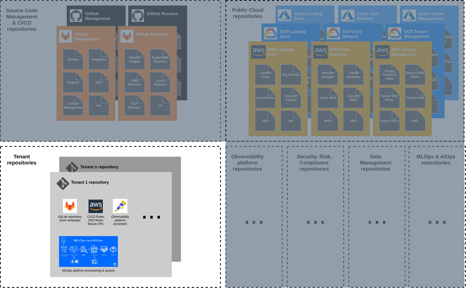
The division of responsibility: Control vs. convenience
This self-similar architecture creates a natural division of responsibility based on the trade-off between control and convenience:
High Control, High Complexity: Infrastructure repositories owned by the platform team handle the most complex infrastructure requirements. These repositories have complete deployment autonomy but require deep expertise to maintain;
Low Control, Low Complexity: Application and tenant owned repositories. What happens here is the complete responsibility and ownership of the tenant team, inheriting guard-rails defined by the platform team in the infrastructure repositories;
The Interface Between Worlds: In a centralised provisioned model, tenant project administration repositories act as the bridge between autonomous and managed worlds. They’re managed by the platform team and deploy tenant-specific CI/CD roles, spoke VPCs, and other non application specific infrastructure.
The IAM role architecture: Access and security
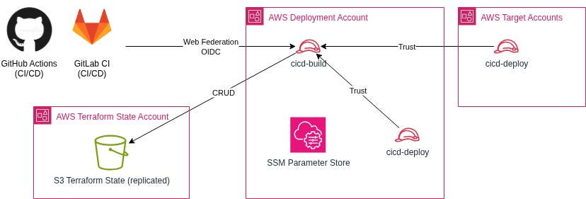
Security in the functional composed repository pattern follows the same self-similar principle. Instead of complex, domain-specific security models, each functional domain uses the same two-role pattern:
Build Role: Manages Terraform state and orchestrates deployments from the central deployment account. Same pattern across all domains.
Deployment Roles: Cross-account roles for deploying to target accounts. Same trust relationship pattern across all domains.
This security pattern means that adding a new functional domain doesn’t require designing new security models. You replicate the existing pattern with domain-specific role names, maintaining consistency while enabling isolation.
As an example, here’s the view of the same type of roles you would find in a large enterprise application of this architecture.
Landing Zone repository IAM roles:
cicd-build-landing-zone: Build role for landing zone repository, created in the CI/CD central account;
cicd-deployment-landing-zone: Deployment role for landing-zone and central compliance infrastructure, created in every account of the organisation;
Core Network repository IAM roles:
cicd-build-network: Build role for core network repository, created in the CI/CD central account;
cicd-deployment-network: Deployment role for core and shared network infrastructure, created in network-related accounts (network, shared services, DNS)
Tenant Project Admin repository IAM roles:
cicd-build-tenant-projects: Build role for tenant management, created in the CI/CD central account;
cicd-deployment-tenant-projects: Deployment capabilities for tenant infrastructure, created in every tenant account;
Tenant repositories IAM Roles:
cicd-build-tenant-x: Build role for specific tenant X, created in the CI/CD central account;
cicd-deployment-tenant-x: Deployment role for tenant X infrastructure, created per tenant project, managed through the Tenant Projects Administration repository;
This security pattern ensures that each level of the architecture has the exact permissions it needs without over-privileging or under-privileging any component. The pattern scales from a handful of accounts to thousands while maintaining security isolation and operational clarity.
Stack dependency management: Loose coupling through interfaces
The functional composed repository pattern eliminates the tight coupling that makes traditional infrastructure changes so difficult. Instead of hard dependencies between repositories, we have loose coupling through stable interfaces. To better understand what this means, let’s briefly discuss the organisation of Terraform state files.
Unless you are using Hashicorp Terraform Cloud, state management in the architecture follows a hierarchical pattern that mirrors the repository organisation:
Central Platform State: Each central platform repository (Landing Zone, Core Network, Tenant Administration) has its own dedicated Terraform state storage, typically S3 Buckets managed via CloudFormation stacks to avoid chicken-and-egg problems (i.e. create the Terraform without the state storage in place);
Tenant Project State: Each tenant project has its own dedicated Terraform S3 state storage buckets managed by Terraform stacks provisioned from the Tenant Administration repository;
Dual-Region Replication: For each Terraform state infrastructure in AWS, a dual-region approach is followed with one region marked as primary and the other as disaster recovery. Changes to any S3 bucket containing state files are replicated to the S3 bucket in the other region;
Now that we understand the Terraform state management and storage, let’s define some isolation rules and stack dependency management for our self-similar architecture:
Within composed-repositories: Stacks can reference each other’s state output values directly (i.e. same functional domain managed by the same team);
Between central repositories: No direct state referencing, object references sharing through parameter store (i.e. different functional domains, may be managed by different teams, complete state isolation);
Tenant repositories: No direct state referencing, integration through APIs or parameter stores (i.e. tenant and application specific domains, complete state isolation);
This hierarchical state management ensures that the blast radius of state corruption or access issues is contained within appropriate boundaries while enabling necessary integration between components where needed.
Implementation strategy: Growing the system
The beauty of self-similar patterns is that you can start small and grow organically. You don’t need to design the entire structure upfront - you can begin with one functional domain and replicate the pattern as your infrastructure grows.
Phase 1: Single Domain: Start with your most critical infrastructure (e.g. Landing Zone) as a single functional domain. Establish the internal structure, deployment patterns, and interface design;
Phase 2: Natural Split: When the domain becomes too large for effective management (usually when it requires coordination between multiple teams), identify the natural split point and create a second domain;
Phase 3: Pattern Replication: As you add new infrastructure capabilities, create new functional domains following the established pattern rather than expanding existing domains beyond their boundaries;
Phase 4: Interface Stabilisation: As domains mature, focus on stabilising their external interfaces to minimise coupling while allowing internal refactoring.
This organic growth prevents the over-engineering that happens when teams try to design the perfect structure upfront while ensuring that the structure can handle unlimited growth.
In conclusion
Mandelbrot discovered that the most complex natural systems follow simple rules repeated at different scales. The functional composed repository pattern applies this insight to infrastructure organisation - high scale complexity managed through self-similar functional domains.
Each domain is complete in itself, following the same internal patterns, deployment approaches, and interface designs. Yet each domain serves its unique purpose within the larger infrastructure ecosystem. This self-similarity provides the cognitive scaffolding that lets engineers understand and manage infrastructure systems of arbitrary complexity.
When you zoom into any functional domain, you find the same organisational patterns you see in the whole system. When you zoom out to see the entire infrastructure ecosystem, you see the same functional boundaries and interface patterns repeated at larger scales.
The alternative is the complexity death spiral that most organisations experience as their infrastructure grows: exponentially increasing coordination overhead, longer deployment cycles, more frequent failures, and eventually the inability to make changes at all without heroic engineering efforts.
The functional composed repository pattern breaks this death spiral by providing a scaling law that remains constant regardless of infrastructure size: organise by function, replicate the pattern, maintain stable interfaces, and let each domain evolve independently within its natural boundaries.
Series Complete: You now have the complete approach for simple (but not over-simplified) infrastructure deployment - from avoiding complexity traps to flowing like water through deployment challenges to organising for high complexity and scale through self-similar patterns.
I invite you to subscribe to my blog, and to read a few of my favourite case-studies describing how some of my clients achieved success in their high-stakes technology projects, using the very same approach described.
Have a great day!
João